Electrical resistivity
Measurement of electrical resistance and its dependence on temperature is commonly used for the detection of structural changes and phase transformations in the material. To be able to successfully understand processes, which occur in the material by measuring electrical resistance, basic theoretical knowledge of electrical conductivity is necessary. The electrical conductivity (σ) is the ability of a substance to conduct an electric current and it is the inverse of the resistivity (ρ):1 σ = 1/ρ
The resistivity is a material property, whilst resistance (R) refers only to a specific sample. The relationship between these two quantities is defined as: ρ = (S/l) R, where S stands for cross-section area of the sample and l for its length.
In most materials (e.g. metals), the current is carried by electrons. The resistivity ρ is then defined by the scattering of the electrons due to the imperfections and thermal vibrations. Matthiessen rule says that the total resistivity ρ total can be approximated by adding up several different terms: ρtotal = ρthermal + ρimpurity + ρdeformation, where the components stand for different types of electron scattering: ρthermal – on thermal vibrations, ρimpurity - on impurities, ρdeformation - on deformation-induced defects.
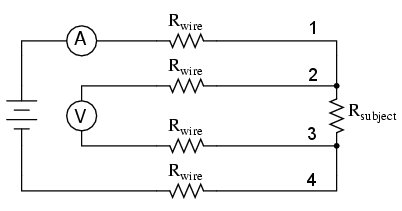
The four-point method is utilized at our department. The circuit scheme of this technique is shown in Fig. 1. Electrical current passes through the two outer probes (1 and 4), while the voltage is measured between the two inner contacts (2 and 3). The wires are welded to respective ends of a sample (Fig. 2)The advantage of this method is that the resistance of connecting leads and their contacts with the sample does not affect the measured resistance. Since the resistance of the voltmeter is much greater than the resistance of the sample, the current which flows through the voltmeter is negligible compared to the flow through the sample. Thus, the resistance of the voltmeter leads and contacts does not play a significant role. Commutated direct current is used to eliminate transient and thermoelectric effects, which arise due to different temperatures on the contacts during voltage measurements and on joints of different materials. The influence of these effects can be eliminated by calculating the average voltage values measured for current flow in both directions.
Electrical resistance can be measured in two different ways:
Measurement of the residual electrical resistance
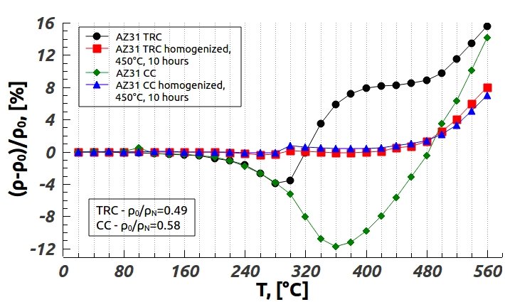
The electrical resistance of a sample is measured at the temperature of liquid nitrogen (-197 °C). At this temperature, ρthermal significantly decreases, which allows us to easily recognize changes that occurred in the material in comparison with its initial state. An example of such measurement is presented in Fig. 3. The sample was in this case heated up to temperature shown at the x-axis and subsequently quenched into water and liquid nitrogen.
In-situ measurement of electrical resistance
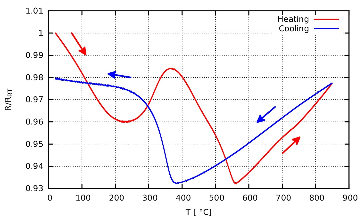
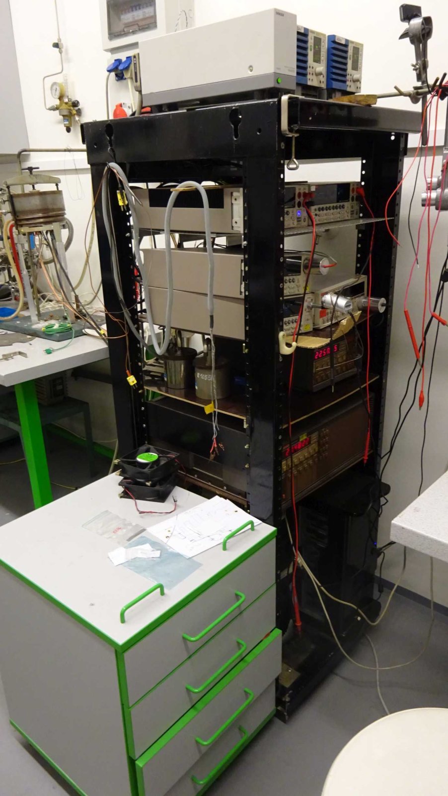
For the in-situ measurements of electrical resistance, a specially designed furnace is utilized. This furnace allows precise heating of the sample in the protective argon atmosphere up to 900 °C. In-situ measurement allows to exactly determine temperatures, which correspond to processes, which occur in the materials during heating (cooling). The temperature profile is fully controllable, therefore the most suitable one can be used. An example of the result of in-situ measurement of electrical resistance during heating and cooling with the heating rate of 5 °C/min is shown in Fig. 4.
Technical specifications
Temperature range:
-197 – 900 °C
Heating rate:
Up to 50 °C/min
Atmosphere:
Inert (Ar), vacuum, air
Sample:
The sample is heated from both sides, therefore flat specimens are preferred. The ideal thickness is bellow 1 mm, maximal length 80 mm and width 50 mm. An example of the sample shape is presented in Fig. 2.
Contact: Mgr. Michal Hájek, Ph.D.